Component Related Documentation
Directional control valves are used to start, stop, and change the direction of flow in hydraulic circuits. Although directional control valves are also available in rotary and poppet styles, the spool type directional control valve is the most common. The spool type design consists of a body with internal passages that are either connected or sealed by a spool sliding along the lands of the valve. Spool valves are sealed by the tight clearance between the moving spool land and the housing. The degree of sealing depends on the clearance, the viscosity of the fluid, and the pressure. As a result, spool valves have slight leakage and cannot hydraulically lock an actuator – as fluid leaks past the clearance between the spool and the valve body the cylinder can drift. Typically, pilot operated check valves are used to prevent cylinders from drifting when spool-type directional control valves are centered. In contrast, poppet valves provide very tight sealing. Directional control valves are primarily designated by their number of port connections (called “ways,” for example, 2-way. 3-way or 4-way, for 2, 3 and 4 ports, respectively), their number of possible positions (most commonly 2 or 3 positions), and how they are actuated or energized. The various ways to actuate or shift a valve are: manual (human actuated: push button, hand lever, foot pedal), mechanical (cam, roller, or a spring), pilot operated (pneumatic or hydraulic pilot), or a solenoid(s). Directional control valves are also designated as normally opened or normally closed. These designations accompany two- and three-position valves as follows: 2-way, 2-position (2/2), normally closed, spring-offset, solenoid operated directional control valve (DCV); 4-way, 3-position (4/3), pilot operated, spring-centered, solenoid controlled DCV; or 2-position, 3-way (2/3), normally open, spring-offset, push button operated DCV.
Safety Related Notes
Before working on this machine, perform lockout-tagout procedures per the rules of your plant. Determine the sources of energy on this machine – electrical, pneumatic and hydraulic – and release or vent sources of stored energy – electrical capacitors, air receivers, and hydraulic accumulators. Shut off sources of power – electrical, pneumatic and hydraulic. Safely block mechanical sources of energy such as loaded springs and loaded machine members, or safely position the machine members so they are unloaded and springs are not under tension. Beware of hot hydraulic fluid and hot surfaces which can cause burns. Never “crack a hydraulic or pneumatic fitting” to check for the presence of stored energy. Hydraulic fluid injection injuries, as well as injection injuries from many other fluids, are extremely serious and must be treated immediately by medical personnel familiar with this type of injury. Loss of body parts or death may result from improperly treated fluid injection injuries! Never use your hands to feel for a hydraulic leak! Review the schematics and think before proceeding to work on the machine to ensure you have made the machine safe to work on.
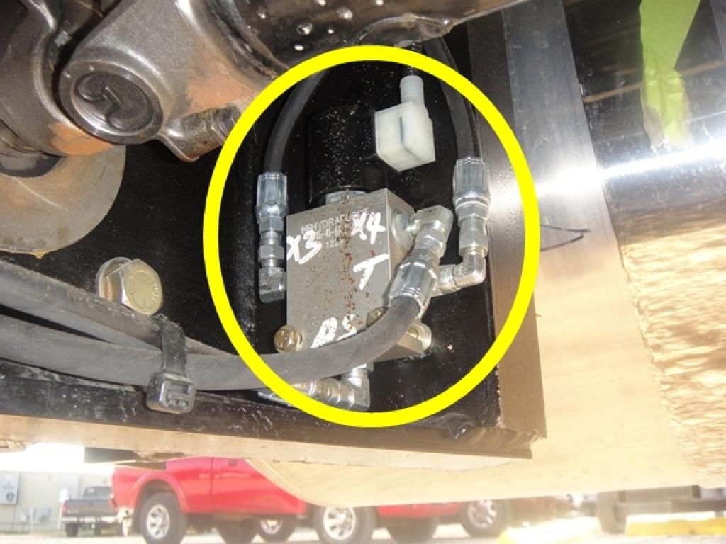
Item:
9
Description:
Dump Valve
Manufacturer:
Hydraforce
Part Number:
SV10-41-6T-N-12DG
Stock Code:
3.30004
Electrical Address:
N/A
Component Application:
This valve is used to dump hydraulic pump control fluid to tank in case of emergency. When actuated this valve allows the pump control pressure to equalize in the pump control piston and the pump will shift to neutral.
