Geroller Motors
Component Related Documentation
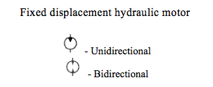
Hydraulic motors are classified as rotary actuators. Motors very closely resemble pumps in construction. However, instead of pushing on the fluid as the pump does, the fluid pushes on the internal surface area of the motor, developing torque. Resistance from the load is encountered and pump flow provides a continuous rotating motion. If enough torque is available to move the load, the motor shaft will rotate. In some circuit designs both the inlet and outlet ports of the motor may be pressurized, so some geroller motors may require an external case drain line in order to prevent failure of the shaft seal due to high case pressure. A geroller motor has an orbital internal gear system. The main components of the geroller motor are the stator, an internal gear with roller teeth; the rotor, an external gear; the drive coupling; an output shaft; a rotary valve that is generally incorporated into the output shaft; and the housing with the ports.
Safety Related Notes
Before working on this machine, perform lockout-tagout procedures per the rules of your plant. Determine the sources of energy on this machine – electrical, pneumatic and hydraulic – and release or vent sources of stored energy – electrical capacitors, air receivers, and hydraulic accumulators. Shut off sources of power – electrical, pneumatic and hydraulic. Safely block mechanical sources of energy such as loaded springs and loaded machine members, or safely position the machine members so they are unloaded and springs are not under tension. Beware of hot hydraulic fluid and hot surfaces which can cause burns. Never “crack a hydraulic or pneumatic fitting” to check for the presence of stored energy. Hydraulic fluid injection injuries, as well as injection injuries from many other fluids, are extremely serious and must be treated immediately by medical personnel familiar with this type of injury. Loss of body parts or death may result from improperly treated fluid injection injuries! Never use your hands to feel for a hydraulic leak! Review the schematics and think before proceeding to work on the machine to ensure you have made the machine safe to work on.
Troubleshooting Document
| Probable Cause | Possible Remedy |
|---|
| Motor-load coupling misaligned |
- Realign motor and load coupling to within .005 in TIR
|
| Motor running away |
- Add flow control to outlet.
- Reduce load
|
| Aeration |
- Check for foaming oil.
- Flush, clean & refill system with fluid having anti-foam additives
|
| Cavitiation |
- Reduce motor speed.
- Check viscosity of fluid. Too high, change to fluid recommended by motor manufacturer.
- Preheat fluid.
- Check for restricted inlet.
- Check for open brake, crossover or make-up valve.
- Check hydraulic pump for cavitations.
|
| Case drain restricted |
- Check drain line, remove and replace.
|
| Sticking vane (on vane motors) |
- Disassemble, clean and reassemble
- Check for proper vane positioning.
|
| Inlet oil is hotter |
- Check for problem at pump (See Pump Troubleshooting section)
- Wrong viscosity oil
- Check oil coolers for obstruction or insufficient cooling capacity.
- Check for low oil level.
|
| Motor slippage too high |
- Disassemble, inspect motor elements: replace if worn or damaged.
|
| Drain line restricted |
- Remove and replace
|
| High GMP flow rate |
- Reduce pump output
- Readjust flow control valve.
|
| Piping incorrect from directional control valve |
- Check piping drawing and correct
|
| Wiring or directional control valve incorrect. |
- Check wiring diagram and correct.
|
| Incorrect valve spool (tandem instead or motor) |
- Disassemble, remove and exchange spools
- Change valve
|
| Load binding |
- Check for linkage and/or other misalignment.
- Loosen and retorque motor mounting bolts.
|
| Open brake, crossover make-Up or system relief valve(s) |
- Check for any all pressure control valves bypassing fluid to tank. Re move repair and/or replace valve(s)
|
| Low operating pressure |
- Check system pressure, make necessary adjustments.
|
| Motor displacement |
- Set adjustments to proper motor distributors
|
| Pump not delivering proper volume and/or pressure |
- Refer to Pump Troubleshooting section.
|
| Seized motor parts. |
- Disassemble, repair or replace parts.
- Replace motor.
|
| External brake needed |
- Consider the addition of a brake all hydraulic motors have internal leakage allowing load drift.
|
| External brake failure |
- Check out the cause of the brake or failure.
|
Item:
82
Description:
Grease Reel Assembly
Manufacturer:
Part Number:
Stock Code:
70.30451
Electrical Address:
N/A
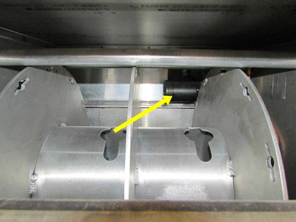
Component Application:
This hydraulic motor is used to rotate the grease reel.