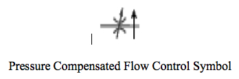
Pressure Compensated Flow Control
Component Related Documentation
The flow rate of fluid through a standard (non-pressure compensated orifice) will vary as the pressure drop across the orifice varies as a result of changes in the load pressure. In order to maintain a constant flow rate regardless of the load pressure, which would cause changes in the pressure drop across a standard orifice, a pressure compensated flow control is often used. A pressure compensated flow control valve is designed to make allowances for pressure changes before or after the orifice. Thus, the speed of the actuator does not change when the load pressure changes. The pressure compensated flow control valve symbol adds an arrow drawn vertically through the orifice on the outlet (downstream side) of the orifice section of the flow control symbol. The primary components of a pressure compensated flow control valve are the housing, a needle valve (either fixed or adjustable), and a pressure compensator valve, often termed a hydrostat, located in series downstream from the needle valve. The hydrostat is a spool type valve which is biased open by a spring on one end. The spring end of the hydrostat is connected to the downstream side of the needle valve and the opposite end of the hydrostat is connected by a pilot drilling to the upstream side of the needle valve. The needle valve is used to control the flow rate through the valve assembly. The hydrostat works to maintain a constant pressure drop across the needle valve, thus maintaining a constant flow rate to the actuator regardless of the load pressure.
Safety Related Notes
Before working on any machine, perform lockout-tagout procedures per the rules of your plant. Determine the sources of energy on this machine – electrical, pneumatic and hydraulic – and release or vent sources of stored energy – electrical capacitors, air receivers, and hydraulic accumulators. Shut off sources of power – electrical, pneumatic and hydraulic. Safely block mechanical sources of energy such as loaded springs and loaded machine members, or safely position the machine members so they are unloaded and springs are not under tension. Beware of hot hydraulic fluid and hot surfaces which can cause burns. Never “crack a hydraulic or pneumatic fitting” to check for the presence of stored energy. Hydraulic fluid injection injuries, as well as injection injuries from many other fluids, are extremely serious and must be treated immediately by medical personnel familiar with this type of injury. Loss of body parts or death may result from improperly treated fluid injection injuries! Never use your hands to feel for a hydraulic leak! Review the schematics and think before proceeding to work on the machine to ensure you have made the machine safe to work on.
Item:
67D
Description:
Fixed Flow Pressure Compensated Flow Control Valve
Manufacturer:
Part Number:
Stock Code:
Electrical Address:
N/A
Component Application:
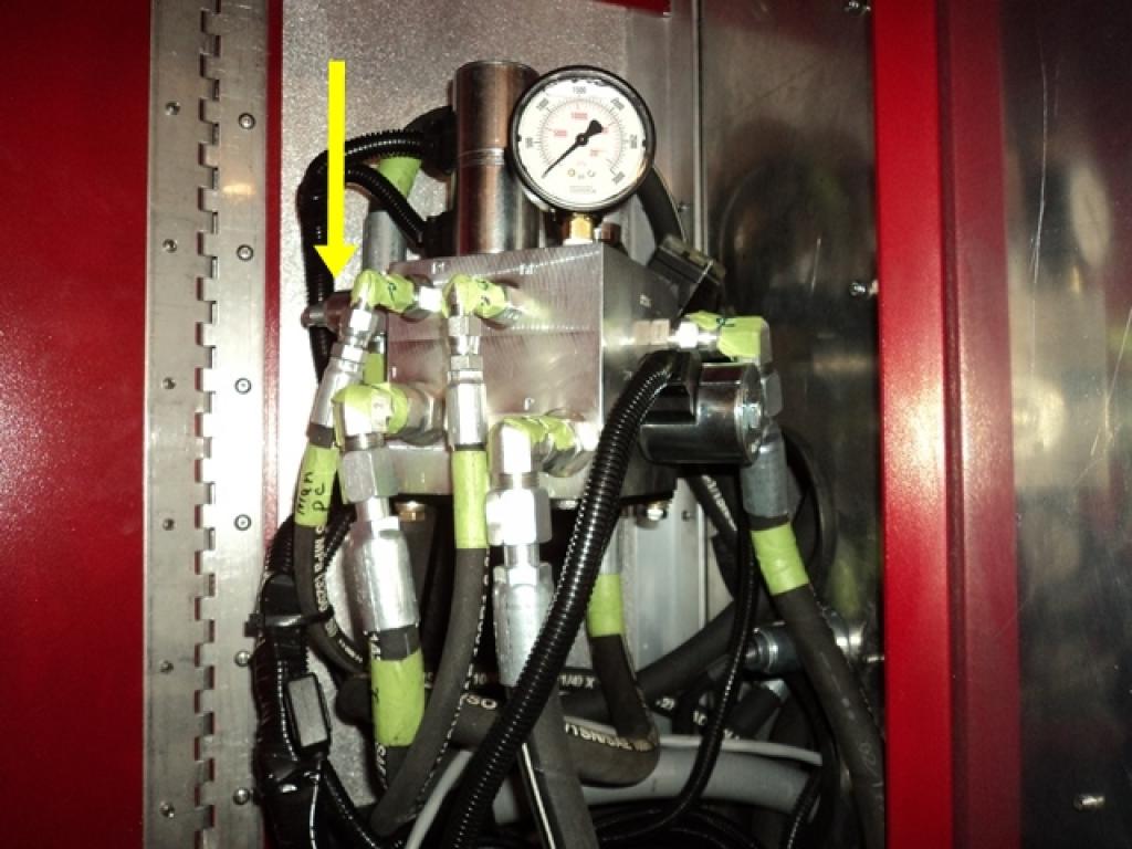
This fixed flow pressure compensated flow control valve is used to provide a constant supply of oil to the grease reel motor when in operation.