Component Related Documentation
Check valve symbols are drawn with a small circle drawn against a 90° vee. This symbolizes the ball or poppet sealing against the valve’s seat, or sealing surface. Free flow is opposite the direction the vee is pointed. As the circle moves into the triangle, the flow is blocked or checked. Conversely, fluid flowing toward the point of the vee lifts the ball or poppet off its seat and fluid flows freely through the valve. A spring symbol drawn over the flow line, touching the circle opposite the vee, indicates a bias spring aids in closing the ball or poppet against the valve’s seat. If the check valve is piloted, either to open or close the valve when pilot pressure is applied, a dashed line is drawn, either to one side of the vee, in the case of pilot-to-open check valves, or to the circle, in the case of pilot-to-close check valves. Pilot-to-close check valves may have the spring located between the vee and the circle indicating the ball or poppet is normally biased off the valve’s seat. The symbol for a shuttle valve is based on a rectangular enclosure. An input flow line connects to the centerpoints of each of the short sides of the enclosure and an output line connects to the centerpoint of one of the long sides. Inside the enclosure are two 90° vees with their points pointing outward, connecting to the input flow lines. A circle is drawn against one of the vees, representing the movable element inside the shuttle valve. Finally, a line is drawn from the inside of one of the vees to the edge of the circle and a perpendicular line extends from this line to connect to the output connection. There two options for symbolizing a quick exhaust valve. The simpler symbol is based on the shuttle valve symbol. Changes are: 1) an exhaust symbol or muffler symbol is connected to the port at one of the short sides of the rectangle. The opposite port becomes the connection to the directional control valve and the output port becomes the cylinder connection port. A pilot line is drawn from the cylinder port connection to the exhaust port end of the envelope.
Safety Related Notes
Before working on this machine, perform lockout-tagout procedures per the rules of your plant. Determine the sources of energy on this machine – electrical, pneumatic and hydraulic – and release or vent sources of stored energy – electrical capacitors, air receivers, and hydraulic accumulators. Shut off sources of power – electrical, pneumatic and hydraulic. Safely block mechanical sources of energy such as loaded springs and loaded machine members, or safely position the machine members so they are unloaded and springs are not under tension. Beware of hot hydraulic fluid and hot surfaces which can cause burns. Never “crack a hydraulic or pneumatic fitting” to check for the presence of stored energy. Hydraulic fluid injection injuries, as well as injection injuries from many other fluids, are extremely serious and must be treated immediately by medical personnel familiar with this type of injury. Loss of body parts or death may result from improperly treated fluid injection injuries! Never use your hands to feel for a hydraulic leak! Never use compressed air to blow dust off yourself or someone else – there is risk of an air injection injury. Review the schematics and think before proceeding to work on the machine to ensure you have made the machine safe to work on.
Item:
49
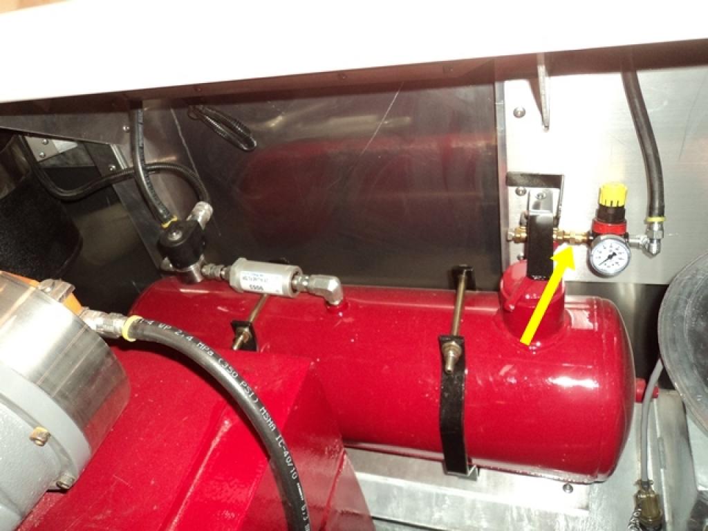
Description:
Line Oil Check Valve
Manufacturer:
Not Provided
Part Number:
Not Provided
Stock Code:
0.40052
Electrical Address:
N/A
Component Application:
This check valve prevents backpressure from following into the air system.
