Component Related Documentation
The maximum pressure of a hydraulic system or the pressure in a circuit can be controlled with the use of a pressure relief valve. Pilot operated pressure relief valves are designed to accommodate greater flow rates than a direct acting pressure relief valve of the same frame size. Pilot operated pressure relief valves consist of two stages. The first stage includes the main spool or poppet which is biased closed by a light (25 to 65 psi) non-adjustable bias spring. This main stage is large enough to handle the maximum flow rating of the valve. A small orifice is drilled in the main spool or poppet to allow pressurized fluid to bleed through the orifice into the bias spring chamber. The second stage is a small direct acting relief valve usually mounted as a cross head on the main valve body, and includes a poppet, spring, and adjustable knob. The purpose of the second stage pressure relief valve is to control the hydraulic pressure of the fluid in the bias spring area of the main poppet or spool. Thus, both the bias spring and hydraulic pressure in the bias spring chamber hold the main spool or poppet closed. When pressure rises to the setpoint of the second stage pressure relief valve, fluid from the bias spring chamber will flow to tank through the second stage valve, thus allowing the main spool or poppet to open, venting fluid to tank, thereby limiting pressure in the circuit. The advantage of a pilot operated pressure relief valve over a direct acting pressure relief valve if the same size is lower pressure rise at the inlet port of the valve as the flow rate through the valve increases.
Safety Related Notes
Before working on this machine, perform lockout-tagout procedures per the rules of your plant. Determine the sources of energy on this machine – electrical, pneumatic and hydraulic – and release or vent sources of stored energy – electrical capacitors, air receivers, and hydraulic accumulators. Shut off sources of power – electrical, pneumatic and hydraulic. Safely block mechanical sources of energy such as loaded springs and loaded machine members, or safely position the machine members so they are unloaded and springs are not under tension. Beware of hot hydraulic fluid and hot surfaces which can cause burns. Never “crack a hydraulic or pneumatic fitting” to check for the presence of stored energy. Hydraulic fluid injection injuries, as well as injection injuries from many other fluids, are extremely serious and must be treated immediately by medical personnel familiar with this type of injury. Loss of body parts or death may result from improperly treated fluid injection injuries! Never use your hands to feel for a hydraulic leak! Review the schematics and think before proceeding to work on the machine to ensure you have made the machine safe to work on.
Item:
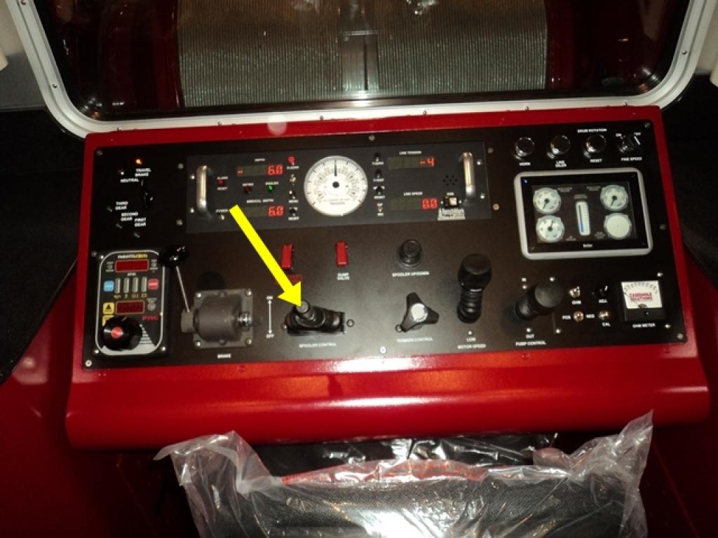
16
Description:
Spooler Control Valve
Manufacturer:
Bosch Rexroth
Part Number:
1-2TH6L06-1X/M05, # R907225176
Stock Code:
0.40075
Electrical Address:
N/A
Component Application:
This valve allows the operator to control how the wire is coiled onto the drum.
